
Page 23 - Green Pin Product Catalogue 2019_EN
P. 23
Side loads
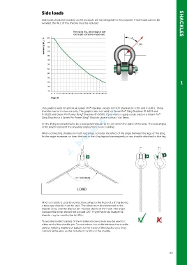
Side loads should be avoided, as the products are not designed for this purpose. If side loads cannot be
avoided, the WLL of the shackle must be reduced: SHACKLES
Remaining WLL percentage at side
load angle α (shackle on pad eye) α
100
remaining WLL % 95 LOAD
90
85
80
75
70
65
60
55
1
50
45
40
0 5 10 15 20 25 30 35 40 45 50 55 60 65 70 75 80 95 90
Angle α
®
This graph is valid for almost all Green Pin shackles, except for ROV Shackles (P-5363 and P-5367). These
®
shackles are for in-line use only. The graph is also not valid for Green Pin Sling Shackles (P-6033 and
P-6013) and Green Pin Power Sling Shackles (P-6043). If you want to apply a side load on a Green Pin
®
®
Sling Shackle or a Green Pin Power Sling Shackle, please contact Van Beest.
®
In-line lifting is considered to be a load perpendicular to the pin and in the plane of the bow. The load angles
in the graph represent the deviating angles from in-line loading.
When connecting shackles to multi-leg slings, consider the effect of the angle between the legs of the sling.
As the angle increases, so does the load in the sling leg and consequently in any shackle attached to that leg.
When a shackle is used to connect two slings to the hook of a lifting device,
a bow type shackle must be used. The slings must be connected to the
shackle body, and the shackle pin must be placed in the hook. The angle
between the slings should not exceed 120°. If symmetrically loaded the
shackle may be used to the full WLL.
To avoid eccentric loading of the shackle a loose spacer may be used on
either end of the shackle pin. Do not reduce the width between the shackle
jaws by welding washers or spacers to the inside of the shackle eyes or by
narrowing the jaws, as this will affect the WLL of the shackle.
23