
Page 86 - Green Pin Product Catalogue 2019_EN
P. 86
WIRE ROPE CLIPS WIRE ROPE CLIPS
Applications
Wire rope clips are used on wire rope eye-loop
connections or complete loops, end-to-end
connections where socketing or splicing is not
feasible or when a temporary joint is required.
Range
®
Green Pin offers a wide range of wire rope clips in specifically standardized models such as EN 13411-5
and DIN wire rope clips. Van Beest also offers a wide range of other wire rope clips to complement the
®
Green Pin assortment.
Design
3
®
Green Pin wire rope clips are drop forged and have a bridge with grooves to tighten the wire rope properly
in the clip; the DIN wire rope clips have a malleable base, without grooves.
Wire rope clips are generally marked with:
• manufacturer’s symbol - e.g. GP
• wire rope diameter in mm or inches - e.g. 13 or 1/2”
• traceability code - e.g. A1
Finish
The finish can be electro-galvanized or hot dipped galvanized.
Certification
Specific details of certificate availability can be found on each product page. Please verify your certification
®
requirements with Green Pin at the time of order.
Instructions for use
Wire rope clips should be inspected before use to ensure that:
• all markings are legible;
• a wire rope clip with the correct dimensions has been selected;
• the nuts or any other locking system cannot vibrate out of position;
• the wire rope clip is free from nicks, gouges and cracks;
• never modify, repair or reshape a wire rope clip by machining, welding, heating or bending as this
may affect their performance.
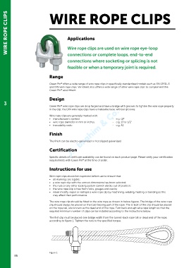
The wire rope clip should be fitted to the wire rope as shown in below figures. The bridge of the wire rope
clip should always be placed on the load bearing part of the rope. The U-bolt of the clip should be placed
on the rope tail, also known as the dead end of the rope. Turn back enough wire rope length so that the
required minimum number of clips can be installed according to the instructions below.
The first clip must be placed one bridge width from the turned-back rope tail or dead end of the rope,
according to figure 1. Tighten the nuts to the specified torque.
Figure 1
86